


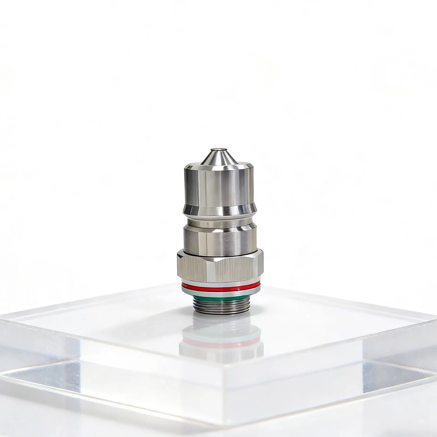
Two Interfaces in One Component
A threaded non-spill liquid cooling coupler combines a permanent or semi-permanent mounting interface with a serviceable quick-disconnect interface. The male thread attaches to a manifold, cold plate, adapter, panel, or pipe component. The opposite end mates with a plug or socket that opens the coolant path during connection and closes it during separation.
These interfaces must be engineered together. Installation torque can distort a seal or connector body, while poor wrench access can lead technicians to load the mating end. The final orientation, connector envelope, hose approach, latch access, and removal path should be checked in the complete assembly.
Thread and Mounting Definition
| Requirement | Define on the drawing or specification |
|---|---|
| Thread identity | Standard, nominal size, pitch, tolerance class, hand, length, runout, lead-in, and gauge method |
| Seal method | Tapered thread sealant, face seal, O-ring, bonded washer, gasket, or another controlled interface |
| Installation | Torque, lubricant or sealant, cure condition, wrench location, orientation, and reuse limits |
| Mating component | Material, thread depth, sealing face, counterbore, edge condition, and strength |
| Retention | Vibration, thermal cycling, anti-rotation, locking method, and inspection witness |
Specify the thread from the released interface definition. Similar-looking parallel and tapered threads can assemble partially while producing poor engagement or an unreliable seal.
Non-Spill Function and Seal Control
The quick-disconnect side may contain moving shutoff elements, springs, seats, dynamic seals, and static seals. Their arrangement controls connection force, valve opening, residual spill, air inclusion, pressure drop, and durability.
Specify compatible elastomer compounds using the actual coolant and temperature range. Control seal storage, cleanliness, lubricant, installation tooling, sharp edges, and assembly damage. Colored identification rings may help distinguish supply and return, connector families, or service roles, but color should never replace controlled part numbers and mistake-proof mechanical compatibility.
Hydraulic and Mechanical Integration
- Flow capacity: use a measured pressure-drop curve for the complete mated pair, not an unmated body diameter.
- Operating state: define whether connection or disconnection occurs depressurized and drained, isolated but filled, or under another approved condition.
- Side load: route hoses and supports so the coupler does not carry continuous bending or torsional load.
- Panel access: reserve hand and tool clearance for mating, lock confirmation, cleaning, and replacement.
- Thermal movement: evaluate expansion of manifolds, hoses, panels, and mating hardware across the temperature range.
- Identification: combine labels or color with keyed interfaces, drawings, and service instructions where cross-connection creates risk.
Installation and Validation Plan
- Inspect the mounting port, thread, sealing face, coupler, and seals for damage or contamination.
- Install using the specified lubricant or sealant, wrench feature, torque, and orientation control.
- Verify the final seal condition and ensure no sealant, cap, or debris enters the flow path.
- Mate the approved counterpart and confirm full engagement, lock indication, and hose strain relief.
- Perform leak and pressure testing with documented medium, temperature, dwell, instrumentation, and limits.
- Measure pressure drop and residual spill when those characteristics are critical to system performance.
- Qualify mating cycles, pressure and temperature cycling, vibration, contamination, and post-test leakage for the intended service life.
For coupling-family selection, read the non-spill quick disconnect guide. For manifold mounting considerations, see four-way coolant manifold design.
Frequently Asked Questions
What does the threaded base of a liquid cooling coupler do?
It mounts the coupler to another fluid component while the opposite end provides the serviceable quick-disconnect interface.
Should the mounting thread also provide the fluid seal?
Only when the released design explicitly uses a thread-sealing method; many assemblies use a separate face seal, O-ring, or washer.
Can colored rings identify connector compatibility?
No. Color can support identification, but controlled part numbers and interface requirements must establish compatibility.
What testing is important after installation?
Verify engagement, retention, leakage, pressure integrity, hydraulic performance where required, and service behavior under defined conditions.