


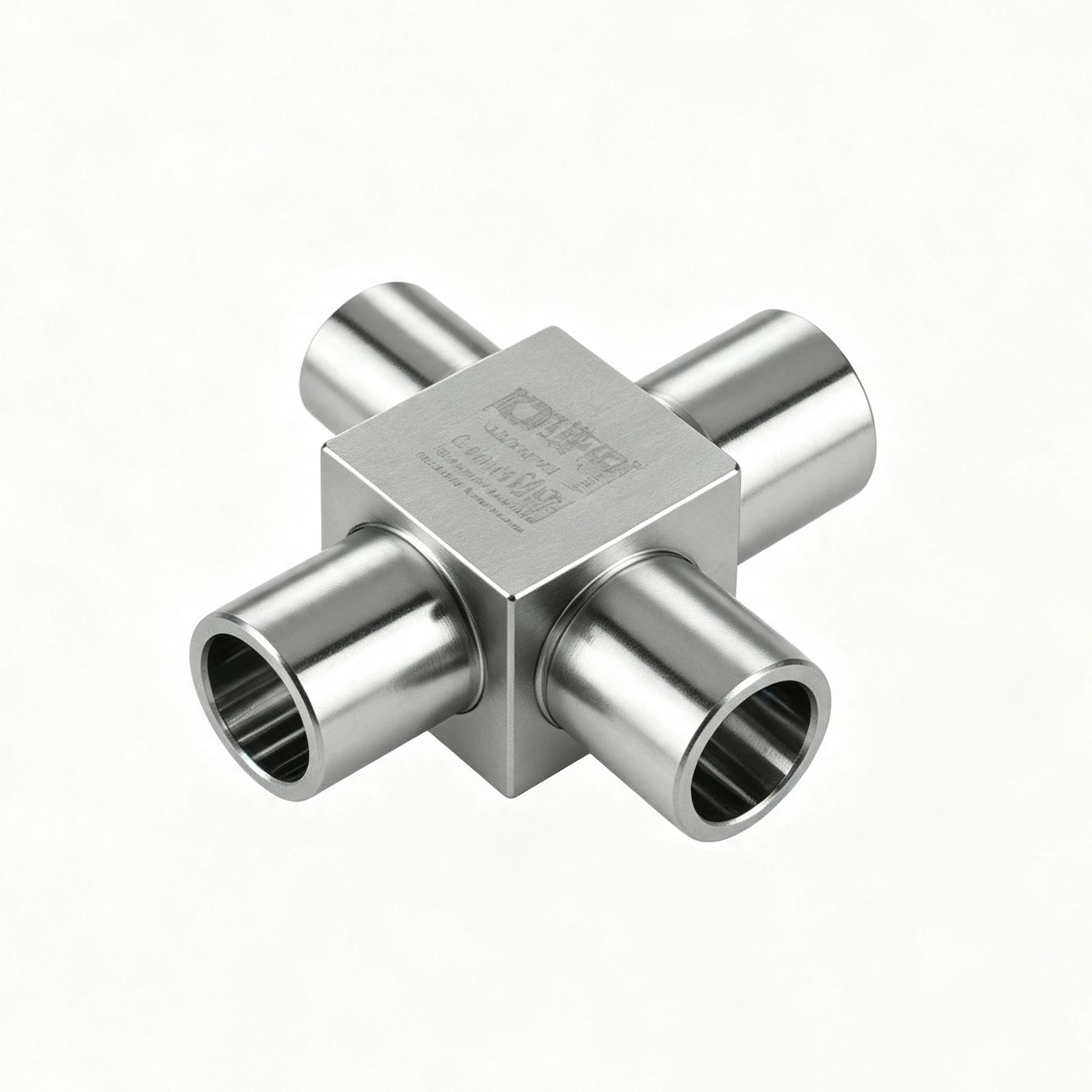
Define the Four-Port Circuit First
A four-way coolant manifold can feed three loads from one inlet, combine three returns, connect two crossing paths, or support another circuit arrangement. Before detailing the block, identify each port as supply, return, branch, vent, drain, sensor, or service connection and define the allowed flow direction in every operating mode.
The same exterior cross shape can hide very different internal architectures. Passages may intersect in a common chamber, cross without communicating, use stepped bores, or include restrictions and closures. A controlled section view is essential for manufacturing, inspection, cleaning, and hydraulic analysis.
Flow Distribution and Pressure Drop
Adding a fourth port increases routing flexibility and hydraulic interaction. Individual branch flow depends on passage geometry plus every connected fitting, hose, cold plate, valve, and elevation change. System calculations should cover coolant properties and pump behavior across startup, normal operation, turndown, transient, and fault conditions.
| Architecture question | What to evaluate |
|---|---|
| One inlet, three outlets | Branch resistance, minimum load flow, balancing strategy, and failure isolation |
| Three returns, one outlet | Backpressure interaction, gas transport, mixing, sensor placement, and drainage |
| Four-way junction | Flow direction changes, recirculation, dead zones, and pressure loss at the common chamber |
| Crossing isolated circuits | Minimum wall, internal leakage risk, inspectability, and proof-pressure method for each circuit |
| Service ports | Capping, valve state, accidental opening, labeling, and maintenance access |
Where branch balance matters, define individual flow limits and measure them. A total flow reading can hide an under-supplied cold plate or battery branch.
CNC Machining Strategy
A compact multi-port block may require several setups for drilling, boring, milling, reaming, port finishing, engraving, and sealing features. Datum strategy should control the relationship among all ports and mounting faces while preserving minimum wall thickness at passage intersections.
Cross holes create burrs and partial edges that can be difficult to reach. The manufacturing plan should include tool breakthrough control, internal deburring, borescope or indirect inspection where appropriate, validated flushing, and a defined particle acceptance method. If ball plugs, threaded plugs, welded caps, or brazed tubes close machining access, include those features in pressure, leak, corrosion, and durability qualification.
Port and Connection Design
- Smooth-bore tube ports: define diameter, roundness, finish, engagement, joining method, shoulder, and edge condition.
- Threaded ports: specify the exact standard, class, depth, runout, gauge, seal method, and installation torque.
- O-ring ports: control groove geometry, lead-in, squeeze, clearance, mating finish, lubricant, and seal compound.
- Quick disconnects: include mating envelope, pressure drop, lock access, side-load control, and verified compatibility.
- Mounting features: establish datums, fastener access, thermal movement, vibration support, and service removal path.
For a lower port-count comparison, read the three-way coolant manifold guide. For connector selection, review non-spill quick-disconnect couplings.
Quality and Validation Plan
- Verify alloy, condition, and lot traceability against the released material requirement.
- Inspect external datums, port position, bore size, sealing geometry, thread, wall, and closure features.
- Confirm internal passage continuity, separation where required, edge condition, and cleanliness.
- Leak test each independent fluid boundary using defined medium, temperature, pressure, dwell, and limits.
- Perform proof-pressure testing with appropriate fixtures and documented safety controls.
- Measure total pressure drop and individual branch flows under representative coolant conditions.
- Qualify pressure cycling, temperature cycling, vibration, corrosion, connector loads, and closure retention as required.
- Dry, cap, package, label, and preserve the verified clean condition through installation.
RFQ Inputs for a Custom Four-Way Manifold
Provide circuit and section drawings, port roles, branch flow targets, allowable pressure drop, coolant, temperature and pressure envelope, materials, all connection and seal details, minimum wall, closure method, cleanliness, inspection, leak and proof testing, hydraulic acceptance, quantity, packaging, traceability, and change-control requirements.
Frequently Asked Questions
What is a four-way coolant manifold?
It is a four-port junction used to divide, combine, or route coolant according to a defined circuit architecture.
How is it different from a three-way manifold?
The extra port adds a branch or routing option together with more hydraulic interaction, machining intersections, sealing interfaces, and inspection points.
How can four manifold branches be balanced?
Control complete branch resistance with passages, restrictions, valves, or connected hardware, then verify individual flows under defined conditions.