


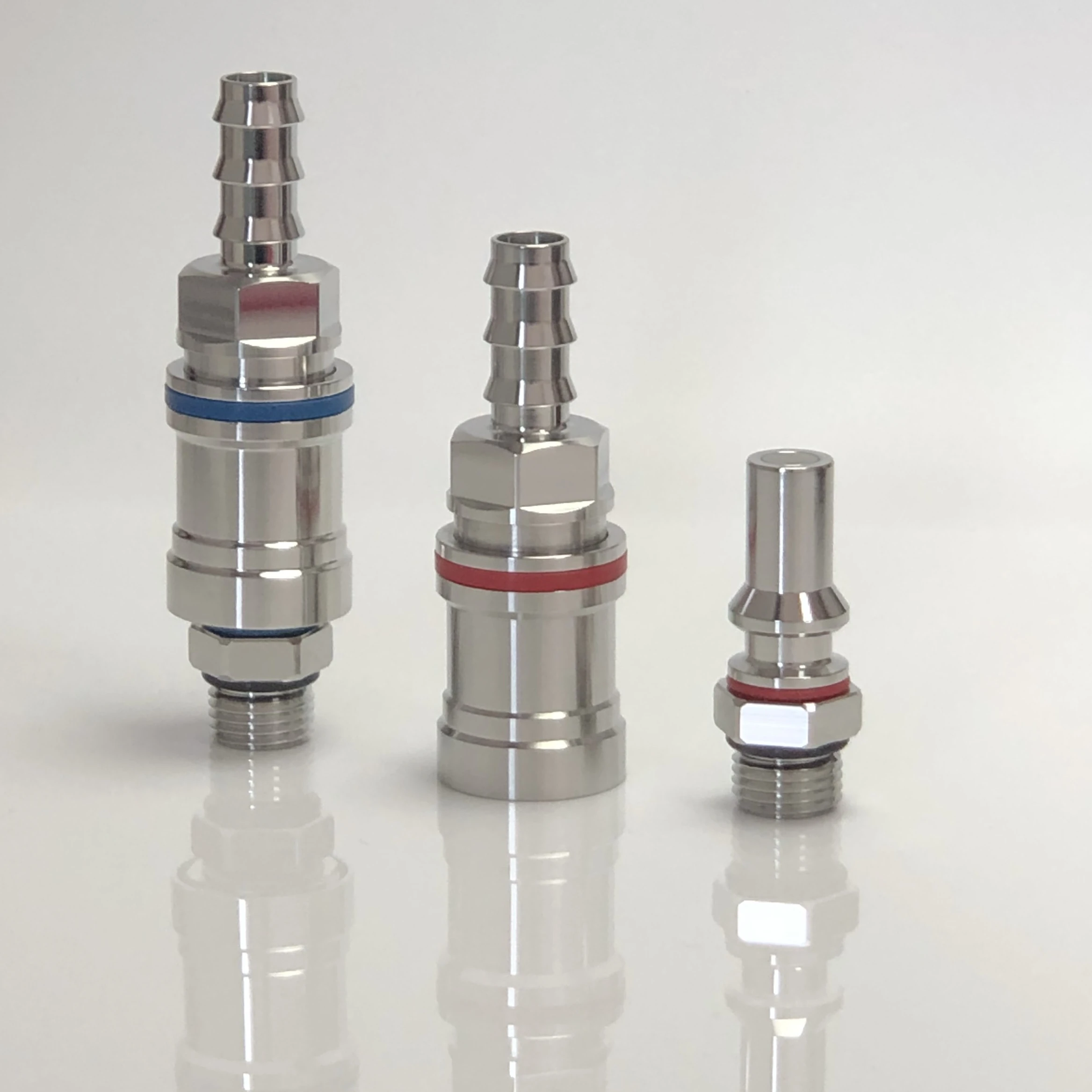
What a Non-Spill Coupling Does
A non-spill quick-disconnect coupling creates a removable connection in a closed coolant loop. Internal shutoff elements are intended to close as the plug and socket separate, reducing fluid release and limiting the volume of air admitted during service. This can simplify replacement of cold plates, GPU trays, rack manifolds, CDUs, or battery cooling modules.
Terms such as dry-break, dripless, and non-spill describe an intended behavior, not a universal performance level. Residual liquid, air inclusion, connection force, valve opening sequence, and pressure drop differ by design. Procurement should therefore use measurable limits and a defined test method instead of relying on the product label.
Core Selection Criteria
| Input | What to define | Why it matters |
|---|---|---|
| Hydraulics | Required flow range, allowable pressure drop, coolant temperature, viscosity, and density | The coupling can become a significant restriction in a high-density cooling loop |
| Pressure | Operating, proof, burst, transient, and connect-or-disconnect pressure conditions | Valve loads, seal behavior, and service procedure depend on the complete envelope |
| Interfaces | Hose barb, thread, tube, panel mount, orientation, envelope, and retention method | A correct fluid interface can still fail when side load or assembly access is poor |
| Materials | Body, spring, valve, plating, lubricant, and all wetted elastomers | Compatibility must be checked against coolant chemistry and the rest of the loop |
| Service life | Mating cycles, vibration, contamination, maintenance interval, and storage | Wear and debris can change leakage, locking, and connection force over time |
Pressure Drop and Flow Sizing
Connector size should not be chosen from hose diameter alone. Obtain the coupling pressure-drop curve over the intended coolant temperature range and include both mating halves, adapters, bends, hoses, manifolds, and cold plates in the system model. Water-glycol mixtures can be substantially more viscous at low temperature, increasing loss when pump margin is already limited.
Use the operating range rather than a single nominal point. Check minimum flow for thermal protection, normal flow for efficiency, and maximum flow for erosion, noise, valve stability, and pump demand. For parallel GPU branches, confirm that coupling variation does not create unacceptable flow imbalance.
Seals, Coolant, and Galvanic Compatibility
Seal selection requires the actual coolant formulation, concentration, additives, temperature, pressure, exposure time, cleaning agents, and storage conditions. A generic label such as EPDM, FKM, or NBR is not enough when compound formulation and approval status affect swelling, compression set, extraction, and low-temperature response.
Metal selection is also a loop-level decision. Stainless steel coolant fittings may offer corrosion resistance, but mixed-metal systems can still create galvanic or chemical risks. Control conductivity, inhibitors, oxygen, pH, contamination, and the total wetted-material list. Review the O-ring liquid cooling adapter guide for sealing-interface details.
Qualification and Incoming Verification
- Dimensional and mating checks: verify controlled interfaces, locking engagement, keying, and interchangeability against released requirements.
- Leak and pressure tests: define medium, temperature, pressure, stabilization, duration, instrumentation, and acceptance limit.
- Residual spill and air inclusion: measure with a repeatable orientation, connection state, cycle history, and fluid condition.
- Flow testing: record pressure drop across the complete mated pair at controlled flow and temperature.
- Durability: include mating cycles, pressure and temperature cycling, vibration, side load, contamination, and post-test leakage.
- Cleanliness: specify particle, oil, residue, drying, capping, packaging, and traceability requirements.
Frequently Asked Questions
What is a non-spill quick-disconnect coupling?
It is a serviceable connector designed to close both fluid paths during separation, limiting coolant release and air entry within specified conditions.
How should a liquid cooling quick disconnect be sized?
Use required flow, allowable pressure drop, coolant properties, temperature, pressure envelope, interfaces, and the complete loop resistance curve.
Does a dry-break connector eliminate every drop of coolant?
No. Residual spill depends on valve design, wear, orientation, pressure, fluid, and the measurement method.